Isometric graphics in Inkscape: Part 2
Last week I posted a quick guide on isometric drawing using Inkscape. In that post, I showed how to obtain images that are projected to the faces of an isometric box.
After my post, I was asked by Biswajit Banerjee on Twitter if I could repeat the process with a more complex example, and he suggested the following schematic
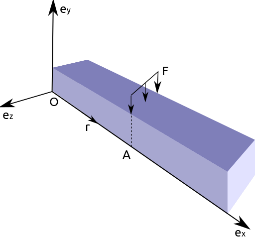
which, I guess, was created in Inkscape using the "Create 3D Box" option.
In this post, I will:
Use the same approach from last week to recreate this schematic
Suggest my preferred approach for drawing this schematic
First approach
I will repeat the cheatsheet from last week. Keep in mind that Inkscape treats clockwise rotation as positive. Opposite to common notation in mathematics.

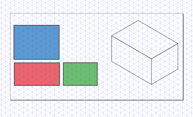
Then, to create a box with desired dimensions we first create each rectangle with the right dimensiones (in parallel projections). In the following example we used faces with aspect ratios 3:2, 2:1 and 4:3. The box at the right is the figure obtained after applying the transformations described in the previous schematic.

We can now proceed, to recreate the desired figure. I don't know the exact dimensions of the box; my guess is that the cross-section was a square and the aspect ratio was 5:1. After applying the transformations to each rectangle we obtain the following (adding some tweaks here and there).

Second approach
For this type of schematic, I would prefer to create an axonometric grid
(File > Document Properties > Grids). After adding the grid to our
canvas it is pretty straightforward to draw the figures in isometric
view. The canvas should look similar to the following image.
We can then draw each face using the grid. If we want to be more precise
we can activate Snap to Cusp Nodes. The following animation shows
the step by step construction.
And we obtain the final image.

Conclusion
As I mentioned, Inkscape can be used for drawing simple figures in isometric projection. Nevertheless, I strongly suggest to use a CAD like FreeCAD for more complicated geometries.
Comments
Comments powered by Disqus